What are you looking for?

 en
en fa
fa fr
fr de
de it
it es
es ar
ar ja
ja cs
cs CN
CN

Design scheme of Containerized ESS with lead-acid battery
2. Design of the container scheme
2.1 Basic introduction to the container
According to the requirements of the project, a 40-foot standard container is selected in consideration of the grouping method of the battery stack, the design and installation of the auxiliary system in the container, and the daily inspection and maintenance. External dimensions: 12192*2438*2591mm. A total of 42 TEUs of 40 feet are required for this project. The container is designed with a static load of 60t and a maximum lifting load of 45t. The main task of the container is to organically integrate lead-acid batteries, communication monitoring and other equipment into a standard 40-foot container unit, which has its own independent power supply system, temperature control system, heat insulation system, flame retardant system, Fire alarm system, electrical interlocking system, mechanical interlocking system, safety escape system, emergency system, fire protection system and other automatic control and safety guarantee systems. The lead-acid battery is installed on the battery bracket, and the bracket is installed at the bottom of the box by means of bolts. BMS cabinets and air conditioners are installed on the floor. The dynamic ring monitoring cabinet adopts wall-mounted installation and integrates an intelligent control unit inside. The power distribution box adopts wall-mounted installation. The power supply wires and environmental equipment monitoring wires in the container are routed internally, and there are no wire grooves and wire pipes on the surface; the power output of the battery and the BMS monitoring and interface wires are routed in grooves, which is convenient for maintenance. The outline drawing of the container is shown below.
Option 1: Use the side maintenance door type

Option 2: Use one side maintenance door type

2.2 The interface characteristics of the container
2.2.1 The mechanical interface characteristics of the container The container can meet the requirements of overall lifting under full load. The container is installed and fixed by bolts as a whole, which is convenient to move. The bolt fixing point is reliably connected with the non-functional conductive conductor of the whole container (the metal shell of the container, etc.), and at the same time, it provides the user with two grounding points that meet the requirements of the electric power standard in the form of copper bars. The degree of protection of the container is IP54. The fixing method is shown in the figure below.

2.2.2 Container electrical interface characteristics The internal equipment of the container adopts dual power supply mode. One is AC power supply mode, the interface is 380V AC; the other is DC independent power supply mode, which provides reliable power guarantee for container environment support equipment and communication monitoring equipment. Under normal circumstances, the power supply of the box is taken from the external AC power supply. When the external power supply fails, it will automatically switch to the DC independent power supply mode and obtain the power supply from the lead-acid battery. The energy storage system provides positive and negative DC power input and output interfaces with a voltage of 672V (colloidal lead-acid batteries, 2V1000AH, 336 in series). The BMS in the box uses RS485 interface or CAN interface to communicate with external PCS, and uses Ethernet interface or 485 interface to communicate with background monitoring, providing battery status information, alarm information, container environment monitoring information, and has "four remote" functions. The entry and exit methods of the power and monitoring communication cables are bottom entry and bottom exit. The power line and monitoring line are routed separately. The power line uses two 1*300mm2 RVV22 cables; the RS485 and Ethernet cables are standard twisted-pair cables with shielding layers.
2.2.3 Container communication interface features The container adopts a unified external communication interface, including two RS485 (ModbusRTU) interfaces, two industrial Ethernet interfaces, and one CAN interface. The type, performance and technical indicators of the communication interface are as follows: 1) RS485: The interface adopts the standard RS485 electrical specification interface. The protocol adopts ModbusRTU mode; the physical layer communication port adopts RS485, and shielded twisted pair is used as the communication medium; the link baud rate of the communication port can be selected from 2400, 4800, 9600 and 19200, and the default is 9600; the link transmission mode is 1 master Mostly half-duplex. The BMS is the master, and the PCS is the slave. 2) Ethernet: The interface adopts RJ-45 port, 10/100Base-T. The text of the communication protocol adopts the standard MODBUS TCP/IP protocol; the BMS is the server, the SCADA monitoring background is the client, and the service port number is 502; after the BMS is started, it is necessary to establish a service listener at 502, and the monitoring background establishes or disconnects the BMS as needed. 3) CAN: reserved CAN interface, using shielded twisted pair, can communicate with PCS and background monitoring system.
2.3.1 Grounding scheme The container provides bolt installation and fixation. The bolt fixing point can be reliably communicated with the non-functional conductive conductor of the entire container (the metal shell of the container that is not charged under normal circumstances, etc.), and at the same time, the container provides users with two grounding points that meet the most stringent electrical standards in the form of copper bars , The grounding point provided to the user must form a reliable equipotential connection with the non-functional conductive conductor of the entire container, and the grounding point is located at the diagonal position of the container. Refer to the figure below for the grounding point of non-functional conductive conductors. The effective cross-sectional area of the conductor in the grounding system is not less than 250mm². Grounding resistance is less than 2Ω. There is a grounding copper bar inside the container. The ground wires of the BMS cabinet and the dynamic environment monitoring cabinet are connected to the internal grounding copper bar. The grounding copper bar in the box is connected to the external copper bar through a 250mm² wire, and the external copper bar is connected to the grounding flat steel. The schematic diagram of the grounding copper bar is as follows.

Ground flat steel size: 40*5*3000mm
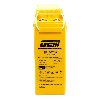
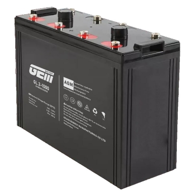
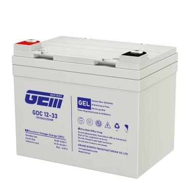
GEM Battery provide various kinds of the batteries for ESS projects, the typical batteries are:
GzV2-600(2V600Ah), GzV2-800(2V800Ah), GzV2-1000(2V1000Ah), GzV2-1500(2V1500Ah), GzV2000(2V2000Ah), GzV2500(2V2500Ah), GzV3000(2V3000Ah) and the 2V GHM Series of Gel batteries
Powered & Powerful!
Distributors and OEM business are warmly welcome.
Get connected with professional lead acid battery manufacturer,
sales@gembattery.com
WhatsApp: +8615959276199

Our team of expert staffs are ready to cooperate with you and to provide professional service. You would get replied immediately with valuable information. Let our cooperation get started soon!


 IPv6 network supported